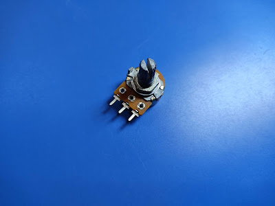
Controlling an LED with Potentiometer/Variable Resistor
Potentiometer - is also known as a Variable Resistor. can generally be used to adjust the resistance from 0 ohms up to there rated values.
Variable resistors/potentiometers generally have three pins: one in the center and one on each side. As the handle of the potentiometer turns, it increases the resistance between one side and the center and decreases the resistance between the center and the opposite side.
Potentiometer are available in linear and logarithmic form. The resistance of linear models changes at a constant rate when turning, while the resistance of the logarithmic model changes slowly at the beginning and then increases rapidly. Logarithmic models are used often in audio amplifiers circuits because they model the human hearing response.
Live demonstration visit: https://youtu.be/4dL55kjGV2U
Note: In this experiment, it is not necessary to use an Arduino board, you can use a 9V battery or you can use a breadboard power supply instead.
Apparatus Required: 1 Breadboard, 1 Potentiometer, 1 LED, Connecting Wires.
Procedure:
- First of all, connect the LED to the breadboard.
- Now connect the Potentiometer to the breadboard.
- Connect the first pin i.e., left pin; black wire to GND (ground).
- Connect the second pin i.e., the middle pin; yellow wire of the potentiometer to the positive terminal of the LED.
- Connect the third pin i.e., the right pin; white wire of the potentiometer to the 5V.
- Lastly, connect the LED negative terminal i.e., blue wire to the GND (ground).
- The connection is completed. Now just adjust the potentiometer to see the fading in and fading out of the LED.
I have this article was helpful to you, if, please let me know.
Thank You!


0 Comments